LL GLOBAL UA
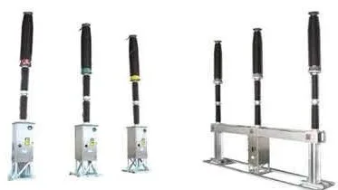
LW38-252

LW38-252

Self-blast SF6 circuit breaker

Three-phase outdoor SF6 circuit breaker for 252 kV, 50 Hz substations and transmission lines. It makes and breaks rated and short-circuit currents and supports fast auto-reclosing.

Key parameters

Rated voltage
252 kV
Rated current
4000 A
Rated short-circuit breaking current
40 kA
Rated operating sequence
O – 0.3 s – CO – 180 s – CO
Mechanical endurance
5,000 operations

General information

LW38-252 is a three-phase self-blast SF6 circuit breaker for outdoor installation in 50 Hz high-voltage AC networks, at substations and on transmission lines. It is designed to make and break rated currents and short-circuit currents, as well as to switch lines, providing protection, control and switching operations in power transmission and transformation systems. It supports opening, closing and fast auto-reclosing, as well as three-pole electrically ganged operation.

The circuit breaker is built on the latest design principles: simple construction, compact dimensions, low material consumption, low required operating energy, high reliability, easy installation and low noise. It is a new generation of high-voltage SF6 circuit breakers.

Service conditions

  • Ambient temperature: −40 °C … +50 °C.
  • Wind pressure: not more than 700 Pa.
  • Altitude: not more than 3000 m.
  • Seismic intensity: not more than 9 degrees.
  • Air pollution level: III.

Ratings of the circuit breaker and operating mechanism

Table 1

ParameterUnitValue
Rated voltagekV252
Rated insulation levelkVsee Table 2
Rated frequencyHz50
Rated currentA4000
Rated short-circuit breaking currentkA40
Rated short-time withstand currentkA40
Rated peak withstand currentkA100
Rated duration of short circuits3
Rated short-circuit making current (peak)kA100
Rated short-line fault breaking currentkA30/36
Rated line-charging breaking currentA125
Rated out-of-phase breaking currentkA10
Total number of rated short-circuit current breaking operationsoperations20
First-pole-to-clear factor1.3
SF6 pressure (at 20 °C)MPasee Table 3
Rated supply voltage of control and auxiliary circuitssee Table 5
Rated operating sequenceO – 0.3 s – CO – 180 s – CO
Mechanical characteristicssee Table 4
Main circuit resistanceµΩ50
Mechanical endurance of the circuit breakeroperations5000
Static terminal loadHorizontal longitudinal FshAN1500
Horizontal transverse FshBN1000
Vertical FtVmN1250
Annual SF6 leakage rate≤ 1 %
SF6 moisture content (×10−6)by volume (V/V)≤ 150
Contact strokemm200 (+4 / −4)
Contact engagement (overtravel)mm28 (+4 / −2)

Table 2. Insulation level

ParameterValue, kV
1 min power-frequency withstand voltage (r.m.s., dry and wet test)Across the isolating distance460+145
Between poles, to earth460
Lightning impulse withstand voltage (peak, full wave 1.2/50 µs)Across the isolating distance1050+200
Between poles, to earth1050
5 min power-frequency withstand voltage (r.m.s.) at zero SF6 gauge pressureAcross the isolating distance220
Between poles, to earth220

Table 3. SF6 pressure (at 20 °C)

ParameterValue, MPa
Rated filling pressure Prm0.4 ± 0.015
Refilling alarm pressure Pam0.35 ± 0.015
Minimum functional pressure Pme0.32 ± 0.015
Pam − Pme0.018 … 0.022
Gas filling pressure for packing and transport0.025

Table 4. Mechanical characteristics

ParameterUnitValue
Opening time (upper and lower limits)ms≤ 34
Closing time (upper and lower limits)ms100
Open–close time (O–C)msfactory tests ≤ 300, in service ≥ 300
Close–open time (C–O)msfactory tests ≤ 60, in service ≥ 60
Pole non-simultaneity on openingms≤ 3
Pole non-simultaneity on closingms≤ 5
Break timems60
Opening speedm/s7.0–7.5
Closing speedm/s2.8–3.8

Table 5. Rated supply voltage of control and auxiliary circuits

ParameterUnitValue
Control and signalling circuit voltageVDC 220
Rated motor voltageVDC 220
Anti-condensation heater circuit voltageVAC 220

All products